wikiHow is a “wiki,” similar to Wikipedia, which means that many of our articles are co-written by multiple authors. To create this article, 13 people, some anonymous, worked to edit and improve it over time.
This article has been viewed 393,249 times.
Learn more...
A diode is a two-terminal electronic device which conducts current in one direction and blocks current in the opposite direction. A diode can also be called a rectifier, which converts AC to DC. Since diodes are essentially "one-way", it's important to know how to determine which end is which. You can usually tell by looking at the markings on the diode, but if they've worn off or don't exist you can use a multimeter to test the diode.
Steps
Examining the Markings
-
1Understand how a diode functions. A diode is composed of an N-type semiconductor joined with a P-type semiconductor. The N-type semiconductor is the negative end of the diode and is called the "cathode". The P-type semiconductor is the positive end of the diode, and is called the "anode".[1]
- If the positive side of a voltage source is connected to the positive end of the diode (the anode), and the negative side is connected to the negative end of the diode (the cathode), the diode will conduct current.
- If the diode is reversed, the current is blocked (up to a limit).
-
2Learn what the diode schematic symbol means. Diodes are indicated on schematics by a symbol (—▷|—) that shows how the diode should be installed. An arrow points at a vertical bar, which has a line continuing out of it.[2]
- The arrow indicates the positive side of the diode, while the vertical bar indicates the negative side. You can think of it as the positive side flowing into the negative side, with the arrow indicating the direction of the flow.
Advertisement -
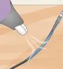
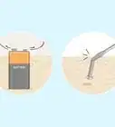
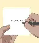
3Look for the large band. If the diode doesn't have the schematic symbol printed on it, look for the ring, band, or line printed on the diode. Most diodes will have a large colored band printed near the negative side (cathode) of the diode. The band will go all the way around the diode.[3]
-
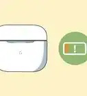
4Identify the positive end of an LED. An LED is a light-emitting diode, and you can usually tell which side is positive by examining the legs. The longer leg is the positive, anode pin.[4]
- If the pins have been trimmed, examine the outer casing of the LED. The pin nearest to the flat edge is the negative, cathode pin.


Using a Multimeter
-
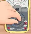
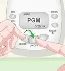
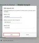
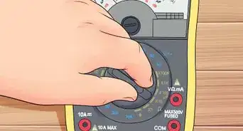
1Turn the multimeter to the "Diode" setting. This is usually indicated by the diode schematic symbol (—▷|—). This mode will allow the multimeter to send some current through the diode, making it easier to test.[5]
- You can still test the diode without the Diode setting. Set the meter to the resistance (Ω) function.
-
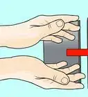
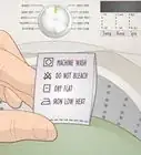
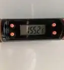
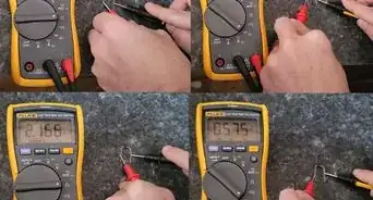
2Connect the multimeter to the diode. Connect the positive lead to the one end of the diode, and the negative end to the other. You should see a reading on the meter's display.[6]
- If your meter has a Diode mode, you will see voltage displayed on the meter if the meter is connected positive-to-positive and negative-to-negative. If its the wrong way, nothing will be displayed.
- If you meter does not have a Diode mode, you will see very low resistance if the meter is connected positive-to-positive and negative-to-negative. If it's the wrong way, you will see very high resistance, sometimes express as "OL".
-
3Test an LED. An LED is a light-emitting diode. Turn the multimeter to the Diode setting. Place the positive lead on one of the pins, and the negative lead on the other. If the LED lights up, the positive lead is touching the positive pin (the anode), and the negative lead is touching the negative pin (the cathode). If it doesn't light up, the leads are touching the opposite pins.[7]


Community Q&A
-
QuestionWhat does a band on one end of a diode indicate?
 Upnorth HereTop AnswererThe line on a diode typically indicates the end known as the cathode (the "minus" end).
 -
QuestionWhy is a diode fitted beween the brushes on a 12 volt DC motor?
 Community AnswerThe motor is composed of coils. You start with voltage being generated in one direction, which includes a magnetic field around the coil. When the current is interrupted, the magnetic field collapses, and the collapsing magnetic field creates a voltage in the opposite polarity to when the current was flowing. That voltage is not only opposite in polarity; it's also a very High Voltage, which is a recipe for frying any circuitry within the first cycle. However, if you put in that diode to forward-bias consistent with the voltage of the spike, it will divert the power from the circuitry, and also limit the spike to 0.7 volts.
 -
QuestionWhat are the diodes with broken bands on them?
 Bruce Hase CooperCommunity AnswerThe band on a diode designates the cathode or negative end of the device.


References
- ↑ https://www.youtube.com/watch?v=Coy-WRCfems
- ↑ http://www.dummies.com/how-to/content/electronics-components-diodes.html
- ↑ https://learn.sparkfun.com/tutorials/polarity/diode-and-led-polarity
- ↑ https://learn.sparkfun.com/tutorials/polarity/diode-and-led-polarity
- ↑ https://www.youtube.com/watch?v=mMXDa5hVzXA
- ↑ http://www.allaboutcircuits.com/vol_3/chpt_3/2.html
- ↑ https://www.youtube.com/watch?v=mMXDa5hVzXA
About This Article
To tell which way round a diode should be, look for a band on one end, which is the positive end. Match this end with a positive voltage and the other end to a negative voltage. If the band has worn off your diode or there isn’t one, you can still use a multimeter to work out which way round it should be. Just turn your multimeter to the diode setting, which is usually shown as an arrow pointing to a vertical line. Then, connect positive and negative voltage to the ends of the diode. If your multimeter displays voltage, the ends are matched. If it displays nothing, swap them round. For more tips, including how to test your diode with a multimeter if it doesn’t have a diode setting, read on!