wikiHow is a “wiki,” similar to Wikipedia, which means that many of our articles are co-written by multiple authors. To create this article, volunteer authors worked to edit and improve it over time.
This article has been viewed 9,268 times.
Learn more...
CAD drafting sheets are important two dimensional drawings that designers and engineers use. Informational, detailed drafting sheets help engineers and designers improve products and parts to become fully functional before production. The steps below will inform you on how to create different views of the part and measure the part using the dimensioning tool. This article will teach users of any skill level in CAD on how to create an organized, professional two dimensional drafting sheet with dimensions in Siemens NX 12.
Steps
Opening a Part File
-
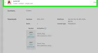
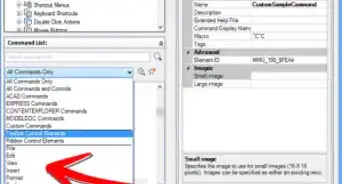
1Move the cursor to “Open” on the top left corner of the screen under the gray “Home” tab.
-
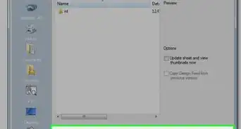
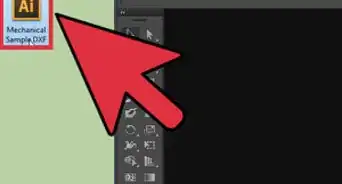
2Click on "OK" when you locate and select the part file. A dialogue box will appear labeled “Open”. Click on the part file, and a preview of the part will appear to the right.
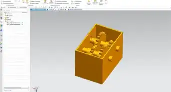
- After opening the part file, the part will load into a gray background with a white 3-D coordinate system on the part.


Loading the Part into Drafting

Creating the Size and Title Block
-
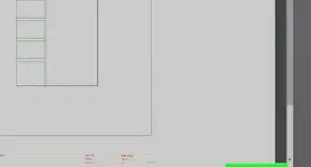
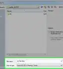
1Choose the appropriate size for the drafting sheet. Look to the left side of the screen under the blue tab labeled "Sheet" and click on “Use Template”. Make sure “A - Size” is already selected and click “OK”.
- Drawing sheets range from A, B, C, D, E, and F sizes with their own specific dimensions in inches in the USA. In this example, the dimensions for a “A” sheet are 8.5 by 11 inches. You can also use the “Standard Size” or “Custom Size” sizes for a drafting sheet. Note: "Standard Size" is E size with the dimensions as 34 by 44 inches.[1]
-
2Click on the “Drawn By” text box in the “Populate Title Block” dialogue box. Type your name and hit the “Enter” key. Click “Close”.


Using the View Creation Wizard
-
1Click the “View Creation Wizard” on the left side of the screen directly below the gray "Home" tab. The "View Creation Wizard" dialogue box will open.
-
2Hit "Next". In the “Part” box to the right of the tabs, it has a green checkmark stating "Select Part". Below "File Name", the part has already been selected automatically in blue.
-
3Select the dashed lines. This is the third selection from the drop-down list under the “Process Hidden Lines” checked box and click on “Next”.
-
4Choose the parent (main) view as “Front” for the part it will turn blue and click “Next”.
- The front view is the most common and popular main view in CAD drafting sheets.
- You can choose other views as the parent view for the part in the “Model Views” list.
-
5Hover over the yellow box with a L shaped figure titled “Parent View”. Click the “Top” view which is directly above the “Parent View”, and the "Top" view will turn yellow too.
- Look to the right of the "View Creation Wizard" dialogue box, the drafting sheet displays the views of the part as you select them. The “Top” view will appear above the “Parent View”.
-
6Select the “Isometric” view, it is to the right of the “Top” view. Uncheck the “Associative Alignment” box under the views in the gray box. Hit the blue button “Finish”.
- The isometric view will appear to the right of the top view on the drafting sheet to the right.
- An isometric view of an object is a 3-D representation with all the angles being equal to each of the axes in the 3-D coordinate system.[2]


Dimensioning the Part
-
1Move the location of the views of the part on the drafting sheet by clicking the border surrounding the part and dragging it to a new location.
- An orange dashed line appears to help align with the other views. Leave white space around the borders for dimensions. Moving the views is not necessary, you can leave the setup as it is.
-
2Click "Rapid" tool under the gray "Home" tab. A dialogue box labeled "Rapid Dimension" will appear to the left.
- The “Rapid” tool shows a lightning bolt with red arrows across it to dimension it.
-
3Zoom in to the drawing sheet to be able to easily select lines for dimensioning. Scroll down on the wheel of a mouse to zoom in or spread your fingers apart for a laptop.
-
4Select the first line you want to dimension from. This is where your measurement starts. Select it in any view besides the isometric view on the drafting sheet.
- This will display an orange dimension if the dimension is a radius, diameter, or length of the line itself. If you want this dimension displayed on the drafting sheet, simply move where you want the dimension and click (it will turn black).
- Keep dimensions outside the border of the views to keep the drafting sheet neat and organized. Please Note: Do not place any dimensions on the isometric view.
-
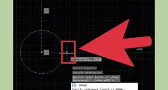
5Select a new first line to dimension from.
- The circled line in the image above is the first line chosen to measure from.
- Sometimes a dialogue box may pop up asking you to specify which line you are choosing. Choose the line you want from the list of options.
-
6Select the second line to dimension to. This is where your measurement ends. Click when you find where to place the dimension.
- The circled line displayed in the image above is the second line chosen to dimension to.
-
7Repeat this process until there are dimensions on the “Top” and “Front” views
- Do not repeat the same dimensions twice in a drawing sheet because this is repeating information.
-
8Move the placement of the dimension by clicking the dimension and dragging it to a new location to make the drafting sheet neat. Unclick for the new location of the dimension.
- It will turn red when hovering over the dimension, then orange when moving it.
-
9Delete any dimension if you make a mistake or you do not want it by right-clicking and selecting the "Delete" option from the list.
-
10Move the dimensions around to leave white space around the edges of the sheet to make the drawing sheet neat and presentable.


Saving the Drafting Sheet


Things You'll Need
- Siemens NX 12