wikiHow is a “wiki,” similar to Wikipedia, which means that many of our articles are co-written by multiple authors. To create this article, 13 people, some anonymous, worked to edit and improve it over time.
wikiHow marks an article as reader-approved once it receives enough positive feedback. In this case, 100% of readers who voted found the article helpful, earning it our reader-approved status.
This article has been viewed 235,564 times.
Learn more...
For the electronics enthusiast, having a 5 volt DC power supply around in your workspace can be very useful. Many op amps, micro controllers, and other digital ICs {integrated circuits} run off 5 volts (although most now take a range of 3-15 volts) . Here is how to build a very simple 5 volt DC power supply that can deliver up to 1.5A of current. You will need to solder together the various components.
Steps
-
1Consider one wire from the AC adapter the positive terminal. Consider the other wire ground. At this point it does not matter which one you choose to be positive or ground, but remember which is which from now on.
-
2Connect the positive wire from the AC adapter to the side of the diode without the stripe marking on it. You are connecting the positive wire to the anode of the diode where current will flow through the diode in only one way to charge the capacitor you will connect later.Advertisement
-
3Locate the lead on the side of the capacitor that has a stripe. Usually this stripe is white and has a minus sign on it. This is the negative side, which you should connect to the ground terminal of the AC adapter.
-
4Connect the remaining terminal of the capacitor to the terminal of the diode with the stripe. That is, connect the positive terminal of the capacitor to the cathode of the diode. The diode allows the current from the transformer to charge the capacitor while stopping the capacitor from discharging back through the transformer on the negative cycle.
-
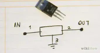
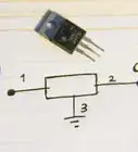
5Connect Pin 1 of the voltage regulator IC to the node where the positive side of the capacitor and striped side of the diode connect. Pin 2 is the ground reference, also called the "common", and should be connected to the ground wire of the AC adapter. Pin 3 is the output. There will be 5 volts held between Pin 3 and ground.


Community Q&A
-
QuestionWhat circuit can I use to make three 12-volt car batteries output 24v DC?
 Community AnswerWhy not use two of them? That would get you exactly 24V. Without knowing more specifics, it's impossible to give an answer, but I think you could use two rather than three.
Warnings
- Running the 5V regulator at high temperatures will shorten its life.⧼thumbs_response⧽
- None of the voltages used in this design are harmful. The AC adapter is the only component that contacts high voltage from the wall outlet. If you want to open the plastic casing of the AC adapter, be sure to do so while it is unplugged from the wall.⧼thumbs_response⧽
- Connecting electrolytic capacitors backwards can cause them to explode. Make sure that the negative terminal of the capacitor (marked with the white stripe) is always at a lower voltage than the positive terminal and that the voltage across the capacitor doesn't exceed the capacitor's voltage rating.⧼thumbs_response⧽
- The 5V regulator will get very hot when drawing a lot of current out of the supply. It may be hot enough to burn you so be careful.⧼thumbs_response⧽
Things You'll Need
- An AC adapter (generic) giving anywhere from 8-30V AC output and up to 1.5 amps of output
- A rectifying diode such as a 1N5392, or equivalent capable of at least 1.5A average forward current and 50V reverse voltage
- A 100uF electrolytic capacitor, radial leaded, rated for at least 35V
- A TL780-05 5V fixed voltage regulator IC or equivalent in a TO-220 package (if it is marked 7805 it will work.)
- A soldering iron and solder (if you're not using a prototype board).