wikiHow is a “wiki,” similar to Wikipedia, which means that many of our articles are co-written by multiple authors. To create this article, volunteer authors worked to edit and improve it over time.
This article has been viewed 12,065 times.
Learn more...
A DC (direct current) motor is a type of motor that uses electrical current to create rotational motion. The speed and acceleration (torque) of the DC motor depends on the amount of current in the circuit. The amount of current going through the circuit depends on many different factors with the two primary variables being voltage and current. When using a fixed voltage to power the DC motor, such as a 9V battery or battery pack, the amount of current depends on the total resistance of the circuit. The two most simple ways to control the resistance is to use resistors and potentiometers. Resistors provide a fixed resistance of any value while a potentiometer provides an adjustable range of resistances. When either are used correctly in a circuit, they provide control over the speed of the DC motor.
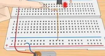
These circuits are most easily done using a breadboard; however, buying screw down components, using electrical tape, or soldering (if you are properly qualified) also works.
Steps
Wiring a Variable Speed DC Motor Circuit
-
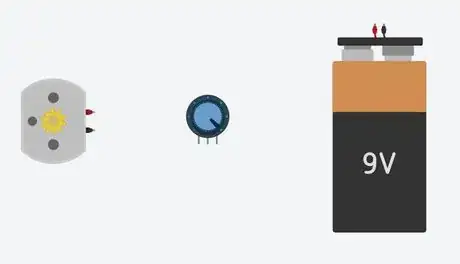
1Get the necessary materials. To build this circuit, a DC power supply, DC motor and a potentiometer are needed.
- The power supply can be any DC battery, power pack, voltage generator, or any device that provides electrical power. *Avoid using high voltages and currents as this can damage the components and be dangerous to work with.*
- The DC motor can be any size or type of electrical motor that uses DC current.
- Three wires are needed. Insulated wires work best as they prevent wires from crossing and the battery from short circuiting.
- A breadboard, electrical tape or solder to make solid connections in the circuit. A tutorial for using breadboards can be found below.
- The potentiometer can be any type that allows manual control of its resistance. The total resistance value of the potentiometer should be fairly high; etc., a 1kΩ potentiometer will work good for a 9V battery. But due to the nature of potentiometers, the motor may not fully stop once it is at its max resistance because current is still flowing. This is where incorporating some kind of switch will allow the motor to be easily stopped when not needed.
-
2Strip the ends of the insulated wires or wrap the middle of the bare wires with tape. About one inch of exposed wire on each end is needed to get a solid connection. Using wire strippers to cut the correct diameter of the wire is easiest, but using scissors or a knife also works. Do not cut off more than the plastic insulation so that the copper wire is exposed. Cutting more than the insulation will damage the wires ability to properly carry current and may prevent the circuit from working.Advertisement
-
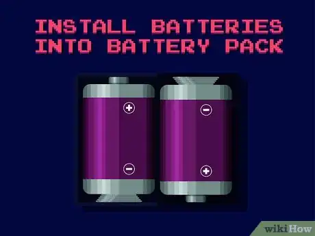
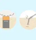
3Prepare the power supply. If using a power pack, install the batteries so the + and - sides are facing the correct directions in the housing. If it can be done, keep the power supply off for now.
-
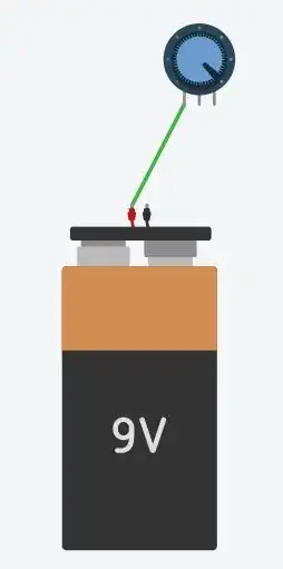
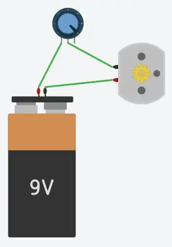
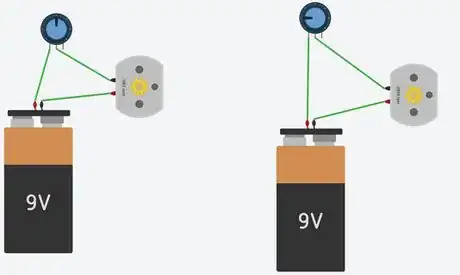
4Connect the potentiometer to the positive or negative terminal of the power supply. One end of the wire must be connected to either outside pin/prong of the potentiometer. Using any method of connecting the wires, securely attach the potentiometer to the power supply using one wire, attached on both ends, or by connecting the components directly together.
-
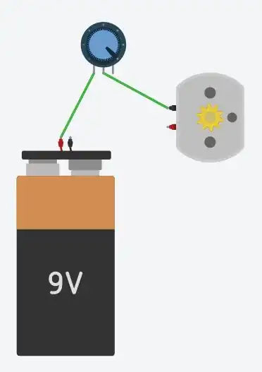
5Connect the potentiometer to one terminal of the DC motor. Attach the wire to the unused middle pin on the potentiometer. This is best done using a wire instead of directly so that the potentiometer can be easily controlled without the motor application interfering.
-
6Connect the other terminal of the DC motor to the unused terminal of the power supply. If the power supply is not off or has no switch, then the motor may begin spinning once it is connected to the power supply. If this causes many problems, a switch may be installed between these components to shut off the circuit when needed. Once both ends of the wire are connected, the circuit will be ready.
-
7Test the circuit. The DC motor should now be spinning if all components are securely connected. Rotating or adjusting the potentiometer should change the speed of the motor with either limit being the motors fastest speed, and the slowest speed the potentiometer can provide. If the motor is not running, check all the connections to make sure the circuit is securely connected. If the motor still doesn't run, check that the battery is not dead by connecting it directly to the motor and replace or recharge if dead. The direction of the motor’s spin can be changed by swapping the wires connected on either terminal of the DC motor. Due to the vast variety of potentiometers, the range of speeds may not be optimal for a specific application and a different type may be needed to have more fine control over the motor or to achieve a lower range of speed.
Wiring a Fixed Speed DC Motor Circuit
-
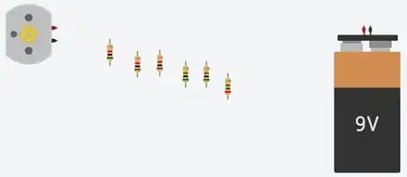
1Get the necessary materials. To build this circuit, a DC power supply, DC motor and resistors are needed.
- The power supply can be any DC battery, power pack, voltage generator, or any device that provides electrical power. *Avoid using high voltages and currents as this can damage the components and be dangerous to work with.*
- The DC motor can be any size or type of electrical motor that uses DC current.
- Three or more wires are needed. Insulated wires work best as they prevent wires from crossing and the battery from short circuiting.
- A breadboard, electrical tape or solder to make solid connections in the circuit. A tutorial for using breadboards can be found below.
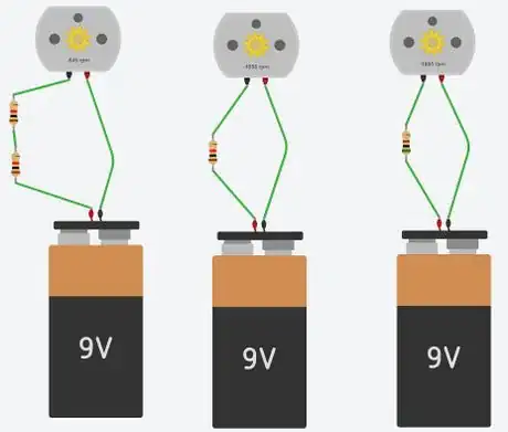
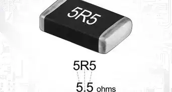
- The resistors can be any value but getting the exact speed needed from the motor requires testing with a certain range of resistors. The values of the resistors add up linearly so it is easy to calculate how to increase or decrease the motors speed by simply adding the values together. For example, two 1kΩ resistors wired together will act the same as a 2kΩ resistor.
-
2Strip the ends of the insulated wires or wrap the middle of the bare wires with tape. About one inch of exposed wire on each end is needed to get a solid connection. Using wire strippers to cut the correct diameter of the wire is easiest, but using scissors or a knife also works. Do not cut off more than the plastic insulation so that the copper wire is exposed. Cutting more than the insulation will damage the wires ability to properly carry current and may prevent the circuit from working.
-
3Prepare the power supply. If using a power pack, install the batteries so the + and - sides are facing the correct directions in the housing. If it can be done, keep the power supply off for now.
-
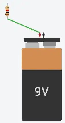
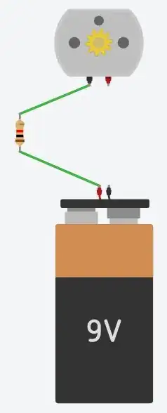
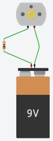
4Connect one resistor to the power supply. One end of the wire must be connected to one end of the resistor. Using a middle-value resistor out of the set first will give you an idea of whether to increase or decrease the resistance depending on the speed of the motor. Using any method of connecting the wires, securely attach the resistor to the power supply using one wire, attached on both ends, or by connecting the components directly together. The amount of resistors here may vary depending on what speed the motor must run at.
-
5Connect the resistor to one terminal of the DC motor. Attach the wire to the unconnected side of the resistor. This is best done using a wire instead of directly so that the resistor(s) are out of the way of the motor application.
-
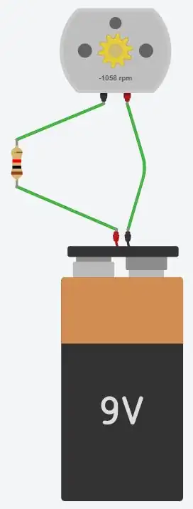
6Connect the other terminal of the DC motor to the unused terminal of the power supply. If the power supply is not off or has no switch, then the motor may begin spinning once it is connected to the power supply. If this causes many problems, a switch may be installed between these components to shut off the circuit when needed. Once both ends of the wire are connected, the circuit will be ready.
-
7Test the circuit. The DC motor should now be spinning if all components are securely connected. The resistance provided by the resistor(s) determines the speed the motor will run. If the motor is not running, check all the connections to make sure the circuit is securely connected. If the motor still doesn't run, check that the battery is not dead by connecting it directly to the motor and replace or recharge if dead. The direction of the motor’s spin can be changed by swapping the wires connected on either terminal of the DC motor. If the motor runs by itself and not when connected to the resistor, the value of the resistor is too high for the motor and a lower resistance is needed.
-
8Fine tune the motors speed. Now that the motor runs, achieving the desired speed is a matter of adding or changing the resistors. To decrease the speed, detach one end of the connected resistor and connect another resistor to that end of the resistor and reattach the disconnected side to the unconnected end of the new resistor. The resistors should be connected in a straight line to get the proper motor speed. To increase the speed, remove all or one of the resistors and reconnect a lower resistance resistor in its place. Many varying resistance resistors can be stacked together to get the exact speed the motor should run at.
Warnings
- Do not use wall outlets or high-voltage sources unless properly educated and trained.⧼thumbs_response⧽
- If both ends of the power supply are touched, the circuit may slightly electrocute you depending on the current being supplied. Although at lower voltages this is no cause for concern other than mild discomfort, high voltage sources can be very dangerous and are not to be used by unqualified individuals.⧼thumbs_response⧽
