wikiHow is a “wiki,” similar to Wikipedia, which means that many of our articles are co-written by multiple authors. To create this article, 13 people, some anonymous, worked to edit and improve it over time.
This article has been viewed 57,382 times.
Learn more...
Wiring a Baldor motor can at first glance look to be a very intimidating task. Yet, with the help of this step by step guide, this task will be become as easy as counting to five. Now, for the purposes of safety, the steps listed below will ONLY demonstrate how to wire a motor for 240V. This should only be used as a basic guide for the process for wiring an AC motor. Please be aware that all steps on this page are subject to change depending on your motors configuration. The goal here is to provide a basic instruction set that will make any future project, whether at home or at work, that much easier to perform.
Steps
-
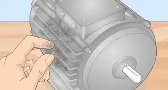
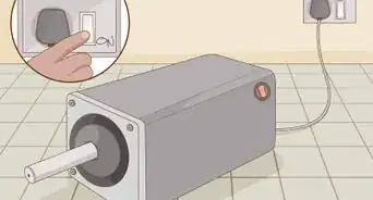
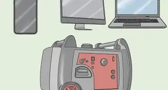
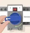
1Check power source. Ensure that any electrical power fed into power cord, is shut off prior to working on motor.
-
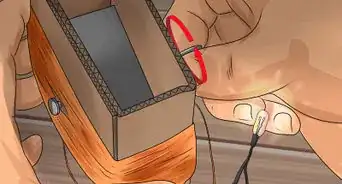
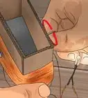
2Prepare power cord. Using a pair of diagonal cutters, cut and remove 3 in of rubber insulation around outside of power cord. Revealing four wires inside cord.
- Remove approx. 3 inches (7.6 cm) of insulation from the outside of the four lines located within the power cord.
- Once for inner lines are visible remove approx. 1in. of insulation from the red, white and black lines, revealing copper wire.
- Be aware that the power lines are referred to as: L1, L2, L3 respectively however there is no specific order to the power lines, meaning these tittles can be used interchangeably.
Advertisement -
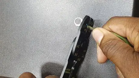
3Connect ground wire to wire terminal. Using a crimping tool, connect ring terminal to the end of ground (green) wire.
-
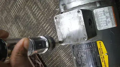
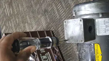
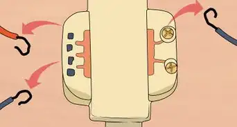
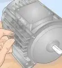
4Examine or check the motor. Using a flat head screwdriver remove four hex head screws securing cover plate of conduit box. This is located on the motor.
-
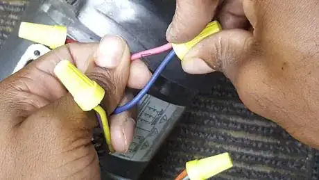
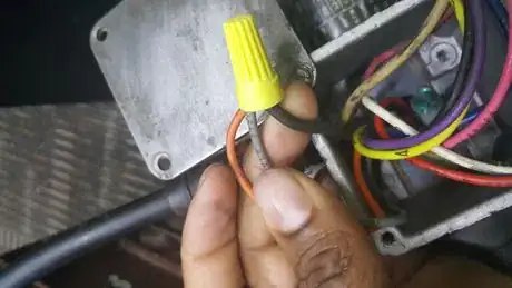
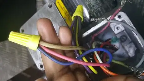
5Prepare Motor. Using standard wire connectors twist and connect wires in the following order:
- 9 to 3
- 8 to 2
- 7 to1
- 4 to 5 to 6
Tip: When making the connections, trim the wires to a uniform length so they will “dress” into the box neatly. This prevents cramming the wires and making a mess.
-
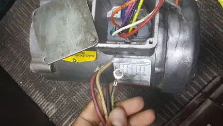
6Connect motor to power source. Feed exposed end of power cord through circular hole of conduit box.
-
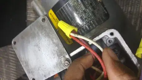
7Wire power cord to motor. Connect power lines to wires located within motor by using standard wire connectors in the following order:
- 9 to 3; L1
- 8 to 2; L2
- 7 to 1; L3
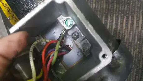
- The ground (green) line is connected separately to a green ground screw located within the conduit box of the motor. (To do this remove screw completely, attach the ground wire to screw. Finally re-insert screw.)
-
8Check all connections. Ensure all of connectors and wires are tight and secure.
- Tug on connectors lightly to confirm proper installation.
-
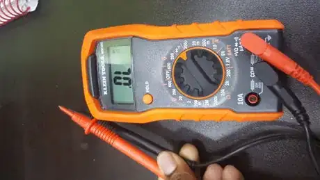
9Check continuity of connections. Using a multi-meter/electrical tester check the continuity of all connections, to do this:
-
10Switch multi-meter/ electrical tester to continuity function.
-
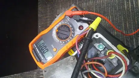
11Place tip of red test lead into electrical connector and the tip of black test lead onto the any pin of the plug.
- Observe multi-meter/ electrical tester for any output of sound. If no sound is observed, place black test lead on a different pin, until sound is observed.
- Repeat this process for every connection in conduit box.
- If continuity does not exist on all four connections, PLEASE check connections to proper confirm installation.
-
12Reattach cover plate. Using a flat head screwdriver insert and secure four hex head screws of cover plate to conduit box.
-
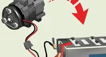
13Plug in motor to ensure proper function.
- If the motor spins in the wrong direction, simply switch the location of two of the power lines, the will reverse the rotation of the motor.
Community Q&A
-
QuestionOn a high-voltage motor with 10T, 11T, 12T as a dot and not going to anything on the wiring diagram, do I leave them all separate and not connected to anything?
 Community AnswerOn a 12-wire motor wired for high voltage (i.e., 480V), 10T, 11T and 12T must be connected together but not connected to anything else. The other 9 wires would be connected as in a 9-wire motor (note in a 9-wire motor, the equivalent of T10, T11 and T12 are internally connected together). L1 to T1, L2 to T2, L3 to T3, T4 to T7, T5 to T8 and T6 to T9. Note: a 9-wire motor can only be connected in a Wye configuration, whereas a 12-wire motor can be connected in either a Wye or Delta configuration. Both 9-wire and 12-wire motors can be connected for high- or low-voltage operation.
Warnings
- Unplug power cord⧼thumbs_response⧽
- Ensure any power source is completely shut off prior to installation.⧼thumbs_response⧽
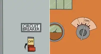
- Shut off power from fuse box/ circuit breaker.⧼thumbs_response⧽
- Ensure that proper PPE (Personal Protective Equipment) is in use.⧼thumbs_response⧽
Things You'll Need
- Wire Strippers
- Diagonal Cutters
- Multi-meter/ Electrical Tester
- Screwdriver flat head: size 2
- Standard wire connectors
- Crimping Tool
- Ring terminal
- Gloves
- Eye protection/ Safety glasses
