X
wikiHow is a “wiki,” similar to Wikipedia, which means that many of our articles are co-written by multiple authors. To create this article, 9 people, some anonymous, worked to edit and improve it over time.
This article has been viewed 13,255 times.
Learn more...
Building a blinking light circuit is a great method to introduce yourself to the electronics world. The art of building circuits that serve a purpose has been around for many years, but the beauty of this circuit is that it can be built by buying only a handful of components that will not cost a lot of money.
Steps
Method 1
Method 1 of 2:
Building a Simple Circuit Manually
-
1Buy all the required materials. You will need 100 Kiloohms Trimmer (Breadboard potentiometer), two 9 Volts batteries, 22 Microfarad Capacitor, one LED light (can be Red, Blue, Green, or White), Breadboard, two 1 Kilohms resistors, one 100 ohms resistor, LM 741 Amplifier, and jumping wires.
-
2Read the manual that comes with the amplifier. The purpose of this step is to learn how the pins are numbered on the amplifier. Usually, the first pin is located on the top left corner (there is usually a little dot to indicate it), and the 8th pin is located on the top right corner.
- pin number 2 is called the inverting input.
- pin number 3 is called the non- inverting input.
- pin number 6 is the amplifier output.
- pin number 4 and pin number 7 are used to power up the circuit.
Advertisement -
3Read the manual that comes with the breadboard. The purpose of this step is to fully understand how the breadboard works:
- Usually the rows are connected.
- The ground is located at one of the sides.
- Some breadboards have different segments, so it’s a good idea to read the manual before building.
-
4Place the amplifier in the middle of the breadboard. The purpose of placing the amplifier in the middle is to have enough space to work with on the top and the bottom. Make sure the little dot on the amplifier is on the top right corner to make identifying pins easier.
-
5Place the trimmer on the breadboard. Note that the trimmer has three pins. However, only the middle and one of the side pins will be used. Make sure that each pin is placed on a different row.
-
6Connect the capacitor to pin number 2 on the amplifier. Note: some capacitors are polarized (the two leads of the capacitor have different lengths).
- Connect the longer lead to pin number 2 on the amplifier.
- Connect the shorter lead to the ground (using jumping wires may be required, it depends how far is the ground pins).
- If the capacitor is not polarized, both leads will have the same length.
-
7Connect the pins for the potentiometer by using jumping wires.
- Connect the middle pin on the potentiometer to pin number 2 on the amplifier.
- Make sure that pin number 2 of the amplifier, one side of the capacitor, and the middle pin of the potentiometer are connected on the same row.
- Connect one of the potentiometer’s side pins to pin number 6 of the amplifier (output pin).
- The remaining pin is unused.
-
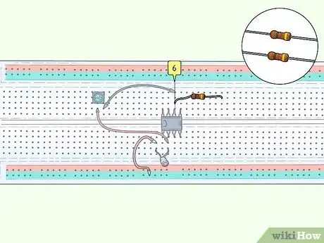
8Place one of 1 kiloohms resistors on the beadboard.
- All resistors have two sides.
- Connect the first side to pin number 6, and the second side to any close empty row.
-
9Place the second 1 kiloohms resistor on the breadboard.
- Connect one side to the same row as the first 1 kiloohms resistor (to the same close empty row).
- Connect the second side to the ground (using jumping wire may be necessary because the resistor is not long enough).
-
10Place the 100 ohms resistor on the breadboard.
- Choose two empty rows in between the two the 1 kiloohms resistors and connect the 100 kiloohms resistor across of them.
- By using a jumping wire, connect the bottom row to the ground.
-
11Place a jumping wire between the row where the two 1 kiloohms resistors intersect and pin number 3.
-
12Place the LED light on the breadboard. Connect the longer lead to pin number 6, and the shorter lead to the same top row for the 100 kiloohms resistor.
-
13Power up the circuit by using two 9 volts batteries. Connect the negative side of the first battery to pin number 4 and the positive side to the ground. Connect the positive side of the second battery to the to pin number 7 and the negative side to the ground.
-
14Turn the knob on the potentiometer to speed up or slow down the blinking. By turning the potentiometer, the total resistance will be changed and that will change the charging and discharging frequency for the capacitor.
Advertisement
Method 2
Method 2 of 2:
Using Multisim Software
-
1Place the LM 741 I the middle of the screen. To place any components in Multisim, click on “place components” in the toolbar, then click on the search button on the side, after selecting the component, double click on it to place it on the screen.
-
2Place the capacitor on the screen. If 22 microfarad is not found, place any capacitor, then double click on it to change the value.
-
3Place a common ground or multiple grounds. to place the ground, go to " place components" and find it under " Power sources".
-
4Double click on the screen to get virtual wires. Double click on the screen at the starting point, then move the cursor to the ending point then click the mouse again. This method has to be used for all required connections.
-
5Connect the capacitor.
- Connect one side to pin number 2 on the amplifier (inverting pin).
- Connect another side to the common ground.
-
6Search for all components. Search and place all the remaining components by using the same method as the previous steps.
-
7Connect the potentiometer. Connect the first side of the potentiometer to pin number 2 and the second side to pin number 6 (output).
-
8Connect the two 1 kiloohms resistor.
- Connect the two of them together.
- Connect one side to pin number 6.
- Connect another side to the common ground.
-
9Connect the non-inverting pin (pin number 3). By using a virtual wire, connect pin number 3 to the intersection between the two 1 kiloohms resistors.
-
10Connect the LED light. Connect the positive side of the LED to one of the leads of the 100 ohms resistor. Connect the second lead of the 100 ohms resistor to the common ground.
-
11Power up the virtual circuit. Power up the virtual circuit by connecting the negative side of the first DC power source (battery) to pin number 4 and the positive side to the common ground. Also, Connect the positive side of the second battery to pin number 7 and the negative side to the common ground.
-
12Change the resistance percentage on the virtual potentiometer. By changing the percentage, the speed of the blinking light will change.
-
13Compare all the connections to the schematic provided in this step. The purpose of this step is to make sure that all connections in the previous steps have been done correctly.
Advertisement
Warnings
- Do not flip the order of the batteries, if that occurred, change the amplifier because it will be burnt.⧼thumbs_response⧽
- If a burning smell appears, Disconnect the batteries immediately.⧼thumbs_response⧽
- Do not place the batteries close to each other.⧼thumbs_response⧽
Advertisement
About This Article
Advertisement


