Transformers change voltages from one value to another. For example, devices such as cell phones, laptops, video games, power tools and small appliances have a transformer (built into their plug-in unit) that changes 120 V into the proper voltage for the device. Transformers are also used at several points in power distribution systems, as shown in . Power is sent long distances at high voltages, as less current is required for a given amount of power (this means less line loss). Because high voltages pose greater hazards, transformers are employed to produce lower voltage at the user's location.
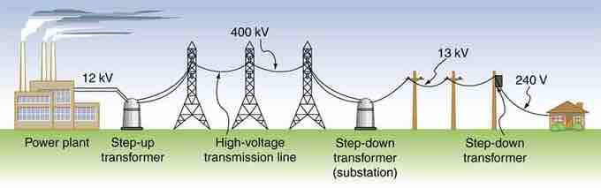
Transformer Setup
Transformers change voltages at several points in a power distribution system. Electric power is usually generated at greater than 10 kV, and transmitted long distances at voltages over 200 kV—sometimes as great as 700 kV—to limit energy losses. Local power distribution to neighborhoods or industries goes through a substation and is sent short distances at voltages ranging from 5 to 13 kV. This is reduced to 120, 240, or 480 V for safety at the individual user site.
The type of transformer considered here is based on Faraday's law of induction, and is very similar in construction to the apparatus Faraday used to demonstrate that magnetic fields can create currents (illustrated in ). The two coils are called the primary and secondary coils. In normal use, the input voltage is placed on the primary, and the secondary produces the transformed output voltage. Not only does the iron core trap the magnetic field created by the primary coil, its magnetization increases the field strength. Since the input voltage is AC, a time-varying magnetic flux is sent to the secondary, inducing its AC output voltage.
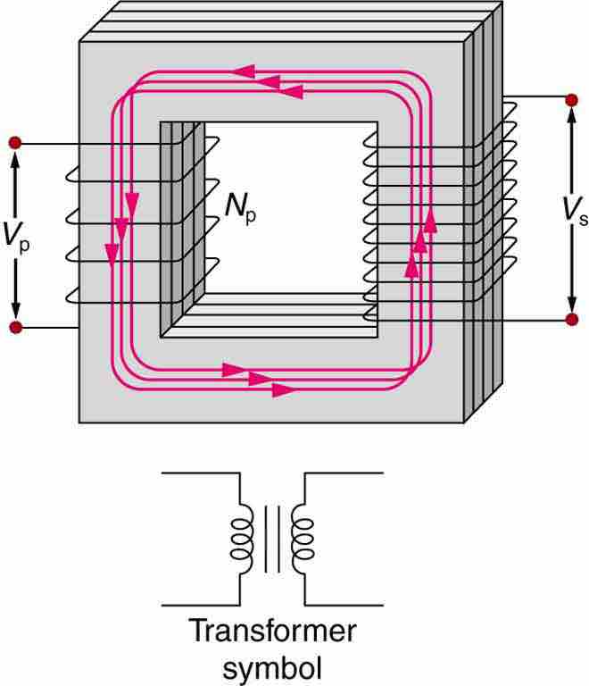
Simple Transformer
A typical construction of a simple transformer has two coils wound on a ferromagnetic core that is laminated to minimize eddy currents. The magnetic field created by the primary is mostly confined to and increased by the core, which transmits it to the secondary coil. Any change in current in the primary induces a current in the secondary.The figure shows a simple transformer with two coils wound on either sides of a laminated ferromagnetic core. The set of coil on left side of the core is marked as the primary and there number is given as N p. The voltage across the primary is given by V p. The set of coil on right side of the core is marked as the secondary and there number is represented as N s. The voltage across the secondary is given by V s. A symbol of the transformer is also shown below the diagram. It consists of two inductor coils separated by two equal parallel lines representing the core.
Transformer Equation
For the simple transformer shown in , the output voltage Vs depends almost entirely on the input voltage Vp and the ratio of the number of loops in the primary and secondary coils. Faraday's law of induction for the secondary coil gives its induced output voltage Vs as:
where Ns is the number of loops in the secondary coil and Δ/Δt is the rate of change of magnetic flux. Note that the output voltage equals the induced EMF (Vs=EMFs), provided coil resistance is small. The cross-sectional area of the coils is the same on either side, as is the magnetic field strength, so /Δt is the same on either side. The input primary voltage Vp is also related to changing flux by:
Taking the ratio of these last two equations yields a useful relationship:
This is known as the transformer equation, which simply states that the ratio of the secondary to primary voltages in a transformer equals the ratio of the number of loops in their coils. The output voltage of a transformer can be less than, greater than or equal to the input voltage, depending on the ratio of the number of loops in their coils. Some transformers even provide a variable output by allowing connection to be made at different points on the secondary coil. A step-up transformer is one that increases voltage, whereas a step-down transformer decreases voltage.
Assuming, as we have, that resistance is negligible, the electrical power output of a transformer equals its input. Equating the power input and output,
Combining this results with the transformer equation, we find:
So if voltage increases, current decreases. Conversely, if voltage decreases, current increases.