Inductance
OVERVIEW
Induction is the process in which an emf is induced by changing magnetic flux. Specifically in the case of electronics, inductance is the property of a conductor by which a change in current in the conductor creates a voltage in both the conductor itself (self-inductance) and any nearby conductors (mutual inductance). This effect derives from two fundamental observations of physics: First, that a steady current creates a steady magnetic field and second, that a time-varying magnetic field induces a voltage in a nearby conductor (Faraday's law of induction). From Lenz's law, a changing electric current through a circuit that has inductance induces a proportional voltage which opposes the change in current (if this wasn't true one can easily see how energy could not be conserved, with a changing current reinforcing the change in a positive feedback loop).
MUTUAL INDUCTANCE
Mutual inductance is the effect of Faraday's law of induction for one device upon another, such as the primary coil in transmitting energy to the secondary in a transformer. See , where simple coils induce emfs in one another.
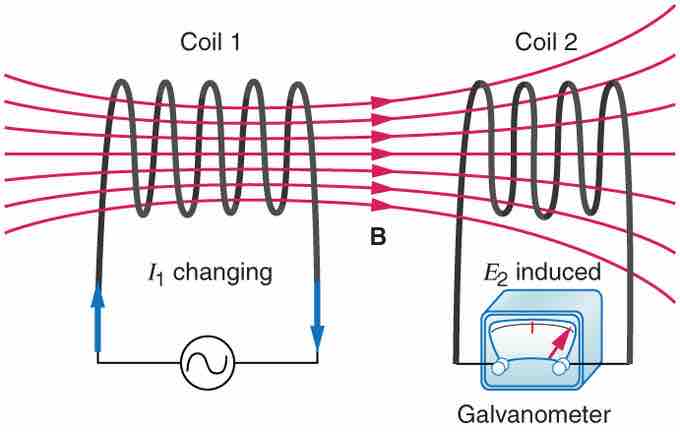
Mutual Inductance in Coils
These coils can induce emfs in one another like an inefficient transformer. Their mutual inductance M indicates the effectiveness of the coupling between them. Here a change in current in coil 1 is seen to induce an emf in coil 2. (Note that "E2 induced" represents the induced emf in coil 2. )
In the many cases where the geometry of the devices is fixed, flux is changed by varying current. We therefore concentrate on the rate of change of current, ΔI/Δt, as the cause of induction. A change in the current I1 in one device, coil 1 in the figure, induces an emf2 in the other. We express this in equation form as
where M is defined to be the mutual inductance between the two devices. The minus sign is an expression of Lenz's law. The larger the mutual inductance M, the more effective the coupling. Units for M are (V⋅s)/A=Ωs, which is named a henry (H), after Joseph Henry (discovered of self-inductance). That is, 1 H=1Ωs.
Nature is symmetric here. If we change the current I2 in coil 2, we induce an emf1 in coil 1, which is given by
where M is the same as for the reverse process. Transformers run backward with the same effectiveness, or mutual inductance M.
A large mutual inductance M may or may not be desirable. We want a transformer to have a large mutual inductance. But an appliance, such as an electric clothes dryer, can induce a dangerous emf on its case if the mutual inductance between its coils and the case is large. One way to reduce mutual inductance M is to counterwind coils to cancel the magnetic field produced. (See ).
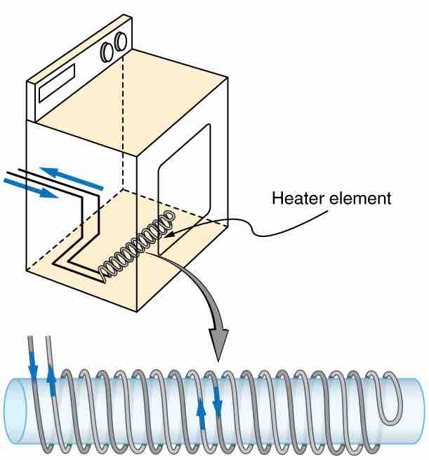
Counterwinding
The heating coils of an electric clothes dryer can be counter-wound so that their magnetic fields cancel one another, greatly reducing the mutual inductance with the case of the dryer.
SELF-INDUCTANCE
Self-inductance, the effect of Faraday's law of induction of a device on itself, also exists. When, for example, current through a coil is increased, the magnetic field and flux also increase, inducing a counter emf, as required by Lenz's law. Conversely, if the current is decreased, an emf is induced that opposes the decrease. Most devices have a fixed geometry, and so the change in flux is due entirely to the change in current ΔI through the device. The induced emf is related to the physical geometry of the device and the rate of change of current. It is given by
where L is the self-inductance of the device. A device that exhibits significant self-inductance is called an inductor, and given the symbol in .
Inductor Symbol
The minus sign is an expression of Lenz's law, indicating that emf opposes the change in current. Units of self-inductance are henries (H) just as for mutual inductance. The larger the self-inductance L of a device, the greater its opposition to any change in current through it. For example, a large coil with many turns and an iron core has a large L and will not allow current to change quickly. To avoid this effect, a small L must be achieved, such as by counterwinding coils as in .
SOLENOIDS
It is possible to calculate L for an inductor given its geometry (size and shape) and knowing the magnetic field that it produces. This is difficult in most cases, because of the complexity of the field created. The inductance L is usually a given quantity. One exception is the solenoid, because it has a very uniform field inside, a nearly zero field outside, and a simple shape. The self-inductance of a solenoid of cross-sectional area A and length ℓ is
It is instructive to derive this equation, but this is left as an exercise to the reader. (Hint: start by noting that the induced emf is given by Faraday's law of induction as emf=−N(Δ/Δt) and, by the definition of self-inductance is given as as emf=−L(ΔI//Δt) and equate these two expressions). Note that the inductance depends only on the physical characteristics of the solenoid, consistent with its definition.