Physics
Textbooks
Boundless Physics
Induction, AC Circuits, and Electrical Technologies
AC Circuits
Physics Textbooks Boundless Physics Induction, AC Circuits, and Electrical Technologies AC Circuits
Physics Textbooks Boundless Physics Induction, AC Circuits, and Electrical Technologies
Physics Textbooks Boundless Physics
Physics Textbooks
Physics
Concept Version 12
Created by Boundless

RL Circuits

An RL circuit consists of an inductor and a resistor, in series or parallel with each other, with current driven by a voltage source.

Learning Objective

  • Describe current-voltage relationship in the RL circuit and calculate energy that can be stored in an inductor


Key Points

    • The energy stored in an inductor is $E=\frac{1}{2}LI^{2}$. It takes time to build up stored energy in a conductor and time to deplete it.
    • When a resistor and an inductor in series are connected to a voltage source, the time-dependent current is given by $I=I_{0}(1-e^{\frac{-t}{\tau}})$. The final current after a long time is $I_0$.
    • The characteristic time constant is given by $\tau=\frac{L}{R}$, where R is resistance and L is inductance. This represents the time necessary for the current in a circuit just closed to go from zero to $0.632\cdot I_0$.
    • When the voltage source is disconnected from the inductor, the current will decay according to $I=I_{0}e^{\frac{-t}{\tau}}$. In the first time interval τ the current falls by a factor of $\frac{1}{e}$ to $0.368\cdot I_0$.

Terms

  • characteristic time constant

    Denoted by $\tau$, in RL circuits it is given by $ \tau=\frac{L}{R}$ where R is resistance and L is inductance. When a switch is closed, it is the time it takes for the current to decay by a factor of 1/e.

  • inductor

    A device or circuit component that exhibits significant self-inductance; a device which stores energy in a magnetic field.


Full Text

RL Circuits

A resistor-inductor circuit (RL circuit) consists of a resistor and an inductor (either in series or in parallel) driven by a voltage source.

Review

Recall that induction is the process in which an emf is induced by changing magnetic flux. Mutual inductance is the effect of Faraday's law of induction for one device upon another, while self-inductance is the the effect of Faraday's law of induction of a device on itself. An inductor is a device or circuit component that exhibits self-inductance.

Energy of an Inductor

We know from Lenz's law that inductors oppose changes in current. We can think of this situation in terms of energy. Energy is stored in a magnetic field. It takes time to build up energy, and it also takes time to deplete energy; hence, there is an opposition to rapid change. In an inductor, the magnetic field is directly proportional to current and to the inductance of the device. It can be shown that the energy stored in an inductor Eind is given by:

$E_{ind}=\frac{1}{2}LI^{2}$.

Inductors in Circuits

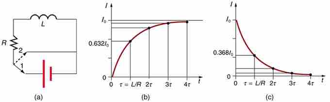
We know that the current through an inductor L cannot be turned on or off instantaneously. The change in current changes the magnetic flux, inducing an emf opposing the change (Lenz's law). How long does the opposition last? Current will flow and can be turned off, but how long does it take? The following figure shows a switching circuit that can be used to examine current through an inductor as a function of time.

Current in an RL Circuit

(a) An RL circuit with a switch to turn current on and off. When in position 1, the battery, resistor, and inductor are in series and a current is established. In position 2, the battery is removed and the current eventually stops because of energy loss in the resistor. (b) A graph of current growth versus time when the switch is moved to position 1. (c) A graph of current decay when the switch is moved to position 2.

When the switch is first moved to position 1 (at t=0), the current is zero and it eventually rises to I0=V/R, where R is the total resistance of the circuitand V is the battery's voltage. The opposition of the inductor L is greatest at the beginning, because the change in current is greatest at that time. The opposition it poses is in the form of an induced emf, which decreases to zero as the current approaches its final value. This is the hallmark of an exponential behavior, and it can be shown (with calculus) that

$I=I_{0}(1-e^{\frac{-t}{\tau }})$ 

is the current in an RL circuit when switched on. (Note the similarity to the exponential behavior of the voltage on a charging capacitor.) The initial current is zero and approaches I0=V/R with a characteristic time constant for an RL circuit, given by:

$\tau=\frac{L}{R}$,

where $\tau$ has units of seconds, since $1H=1\Omega\cdot s$. In the first period of time $\tau$, the current rises from zero to 0.632I0, since I=I0(1−e−1)=I0(1−0.368)=0.632I0. The current will be 0.632 of the remainder in the next time. A well-known property of the exponential function is that the final value is never exactly reached, but 0.632 of the remainder to that value is achieved in every characteristic time $\tau$. In just a few multiples of the time $\tau$, the final value is very nearly achieved (see part (b) of above figure).

The characteristic time $\tau$ depends on only two factors, the inductance L and the resistance R. The greater the inductance L, the greater it is, which makes sense since a large inductance is very effective in opposing change. The smaller the resistance R, the greater $\tau$ is. Again this makes sense, since a small resistance means a large final current and a greater change to get there. In both cases (large L and small R) more energy is stored in the inductor and more time is required to get it in and out.

When the switch in (a) is moved to position 2 and cuts the battery out of the circuit, the current drops because of energy dissipation by the resistor. However, this is also not instantaneous, since the inductor opposes the decrease in current by inducing an emf in the same direction as the battery that drove the current. Furthermore, there is a certain amount of energy, (1/2)LI02, stored in the inductor, and it is dissipated at a finite rate. As the current approaches zero, the rate of decrease slows, since the energy dissipation rate is I2R. Once again the behavior is exponential, and I is found to be

$I=I_{0}e^{\frac{-t}{\tau}}$

In (c), in the first period of time $\tau=L/R$ after the switch is closed, the current falls to 0.368 of its initial value, since I=I0e−1=0.368I0. In each successive time $\tau$, the current falls to 0.368 of the preceding value, and in a few multiples of $\tau$, the current becomes very close to zero.

[ edit ]
Edit this content
Prev Concept
Inductance
RLC Series Circuit: At Large and Small Frequencies; Phasor Diagram
Next Concept
Subjects
  • Accounting
  • Algebra
  • Art History
  • Biology
  • Business
  • Calculus
  • Chemistry
  • Communications
  • Economics
  • Finance
  • Management
  • Marketing
  • Microbiology
  • Physics
  • Physiology
  • Political Science
  • Psychology
  • Sociology
  • Statistics
  • U.S. History
  • World History
  • Writing

Except where noted, content and user contributions on this site are licensed under CC BY-SA 4.0 with attribution required.