Physics
Textbooks
Boundless Physics
Induction, AC Circuits, and Electrical Technologies
AC Circuits
Physics Textbooks Boundless Physics Induction, AC Circuits, and Electrical Technologies AC Circuits
Physics Textbooks Boundless Physics Induction, AC Circuits, and Electrical Technologies
Physics Textbooks Boundless Physics
Physics Textbooks
Physics
Concept Version 11
Created by Boundless

Resonance in RLC Circuits

Resonance is the tendency of a system to oscillate with greater amplitude at some frequencies—in an RLC series circuit, it occurs at ν0=12πLC\nu_0 = \frac{1}{2\pi\sqrt{LC}}ν​0​​=​2π√​LC​​​​​1​​.

Learning Objective

  • Compare resonance characteristics of higher- and lower-resistance circuits


Key Points

    • Resonance condition of an RLC series circuit can be obtained by equating XL and XC, so that the two opposing phasors cancel each other.
    • At resonance, the effects of the inductor and capacitor cancel, so that Z=R, and Irms is a maximum.
    • Higher-resistance circuits do not resonate as strongly compared to lower-resistance circuits, nor would they be as selective in, for example, a radio receiver.

Terms

  • rms

    Root mean square: a statistical measure of the magnitude of a varying quantity.

  • impedance

    A measure of the opposition to the flow of an alternating current in a circuit; the aggregation of its resistance, inductive and capacitive reactance. Represented by the symbol Z.

  • reactance

    The opposition to the change in flow of current in an alternating current circuit, due to inductance and capacitance; the imaginary part of the impedance.


Full Text

Resonance is the tendency of a system to oscillate with greater amplitude at some frequencies than at others. Frequencies at which the response amplitude is a relative maximum are known as the system's resonance frequencies. To study the resonance in an RLC circuit, as illustrated below, we can see how the circuit behaves as a function of the frequency of the driving voltage source.
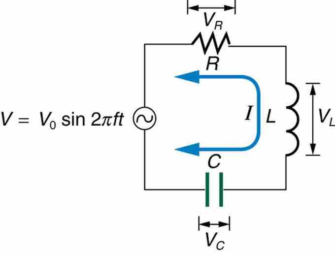
RLC Series Circuit

An RLC series circuit with an AC voltage source. f is the frequency of the source.

Combining Ohm's law, Irms=Vrms/Z, and the expression for impedance Z from

Z=R2+(XL−XC)2Z = \sqrt{R^2 + (X_L - X_C)^2}Z=√​R​2​​+(X​L​​−X​C​​)​2​​​​​ gives

Irms=VrmsR2+(XL−XC)2I_{rms} = \frac{V_{rms}}{\sqrt{R^2 + (X_L - X_C)^2}}I​rms​​=​√​R​2​​+(X​L​​−X​C​​)​2​​​​​​​V​rms​​​​,

where Irms and Vrms are rms current and voltage, respectively. The reactances vary with frequency ν\nuν, with XL large at high frequencies and XC large at low frequencies given as:

XL=2πνL,XC=12πνCX_L = 2\pi \nu L, X_C = \frac{1} {2\pi \nu C}X​L​​=2πνL,X​C​​=​2πνC​​1​​.

At some intermediate frequency ν0\nu_0ν​0​​, the reactances will be equal and cancel, giving Z=R —this is a minimum value for impedance, and a maximum value for Irms results. We can get an expression for ν0\nu_0ν​0​​ by taking XL=XC. Substituting the definitions of XL and XC yields:

ν0=12πLC\nu_0 = \frac{1}{2\pi \sqrt{LC}}ν​0​​=​2π√​LC​​​​​1​​.

ν0\nu_0ν​0​​ is the resonant frequency of an RLC series circuit. This is also the natural frequency at which the circuit would oscillate if not driven by the voltage source. At ν0\nu_0ν​0​​, the effects of the inductor and capacitor cancel, so that Z=R, and Irms is a maximum. Resonance in AC circuits is analogous to mechanical resonance, where resonance is defined as a forced oscillation (in this case, forced by the voltage source) at the natural frequency of the system.

The receiver in a radio is an RLC circuit that oscillates best at its ν0\nu_0ν​0​​. A variable capacitor is often used to adjust the resonance frequency to receive a desired frequency and to reject others. is a graph of current as a function of frequency, illustrating a resonant peak in Irms at ν0=f0\nu_0 = f_0ν​0​​=f​0​​. The two curves are for two different circuits, which differ only in the amount of resistance in them. The peak is lower and broader for the higher-resistance circuit. Thus higher-resistance circuits do not resonate as strongly, nor would they be as selective in, for example, a radio receiver.

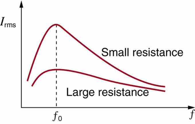
Current vs. Frequency

A graph of current versus frequency for two RLC series circuits differing only in the amount of resistance. Both have a resonance at f0, but that for the higher resistance is lower and broader. The driving AC voltage source has a fixed amplitude V0.

[ edit ]
Edit this content
Prev Concept
Inductors in AC Circuits: Inductive Reactive and Phasor Diagrams
Power
Next Concept
Subjects
  • Accounting
  • Algebra
  • Art History
  • Biology
  • Business
  • Calculus
  • Chemistry
  • Communications
  • Economics
  • Finance
  • Management
  • Marketing
  • Microbiology
  • Physics
  • Physiology
  • Political Science
  • Psychology
  • Sociology
  • Statistics
  • U.S. History
  • World History
  • Writing

Except where noted, content and user contributions on this site are licensed under CC BY-SA 4.0 with attribution required.