Physics
Textbooks
Boundless Physics
Induction, AC Circuits, and Electrical Technologies
AC Circuits
Physics Textbooks Boundless Physics Induction, AC Circuits, and Electrical Technologies AC Circuits
Physics Textbooks Boundless Physics Induction, AC Circuits, and Electrical Technologies
Physics Textbooks Boundless Physics
Physics Textbooks
Physics
Concept Version 9
Created by Boundless

Inductors in AC Circuits: Inductive Reactive and Phasor Diagrams

In an AC circuit with an inductor, the voltage across an inductor "leads" the current because of the Lenz' law.

Learning Objective

  • Explain why the voltage across an inductor "leads" the current in an AC circuit with an inductor


Key Points

    • With an inductor in an AC circuit, the voltage leads the current by one-fourth of a cycle, or by a 90º phase angle.
    • The rms current Irms through an inductor L is given by a version of Ohm's law: $I_{rms} = \frac{V_{rms}}{X_L}$ . XL is called the inductive reactance, given as $X_L = 2\pi \nu L$ .
    • Phasors are vectors rotating in counter-clockwise direction. A phasor for an inductor shows that the voltage lead the current by a 90º phase.

Terms

  • phasor

    A representation of a complex number in terms of a complex exponential.

  • rms

    Root mean square: a statistical measure of the magnitude of a varying quantity.

  • Lenz's law

    A law of electromagnetic induction that states that an electromotive force, induced in a conductor, is always in such a direction that the current produced would oppose the change that caused it; this law is a form of the law of conservation of energy.


Full Text

Suppose an inductor is connected directly to an AC voltage source, as shown in . It is reasonable to assume negligible resistance because in practice we can make the resistance of an inductor so small that it has a negligible effect on the circuit. The graph shows voltage and current as functions of time. (b) starts with voltage at a maximum. Note that the current starts at zero, then rises to its peak after the voltage driving it (as seen in the preceding section when DC voltage was switched on).

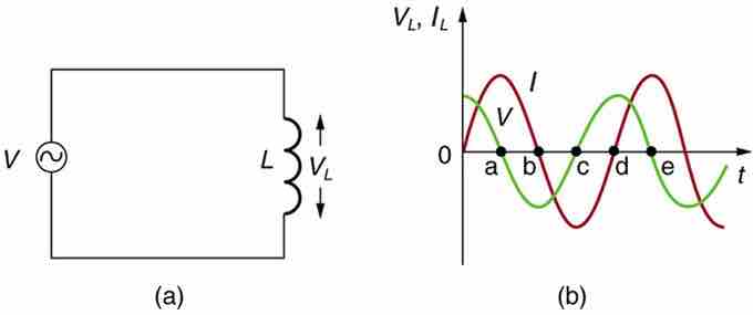
AC Voltage Source in Series with an Inductor

(a) An AC voltage source in series with an inductor having negligible resistance. (b) Graph of current and voltage across the inductor as functions of time.

When the voltage becomes negative at point a, the current begins to decrease; it becomes zero at point b, where voltage is its most negative. The current then becomes negative, again following the voltage. The voltage becomes positive at point c where it begins to make the current less negative. At point d, the current goes through zero just as the voltage reaches its positive peak to start another cycle. Hence, when a sinusoidal voltage is applied to an inductor, the voltage leads the current by one-fourth of a cycle, or by a 90º phase angle.

Current lags behind voltage, since inductors oppose change in current. Changing current induces an emf . This is considered an effective resistance of the inductor to AC. The rms current Irms through an inductor L is given by a version of Ohm's law: $I_{rms} = \frac{V_{rms}}{X_L}$ where Vrms is the rms voltage across the inductor and $X_L = 2\pi \nu L$ with $\nu$ the frequency of the AC voltage source in hertz. XL is called the inductive reactance. Because the inductor reacts to impede the current, XL has units of ohms (1 H=1 Ωs, so that frequency times inductance has units of (cycles/s)(Ωs)=Ω), consistent with its role as an effective resistance.

Phasor Representation

The voltage across an inductor "leads" the current because of the Lenz's law. Therefore, the phasor representing the current and voltage would be given as in . Again, the phasors are vectors rotating in counter-clockwise direction at a frequency
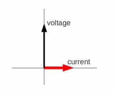
 $\nu$ (you can see that the voltage leads the current). Subsequent Atoms will discuss how these phasors can be used to analyze RC, RL, LC, and RLC circuits.

Phasor Diagram

Phasor diagram for an AC circuit with an inductor.

Phasors for Inductors in AC Circuits

[ edit ]
Edit this content
Prev Concept
Capacitors in AC Circuits: Capacitive Reactance and Phasor Diagrams
Resonance in RLC Circuits
Next Concept
Subjects
  • Accounting
  • Algebra
  • Art History
  • Biology
  • Business
  • Calculus
  • Chemistry
  • Communications
  • Economics
  • Finance
  • Management
  • Marketing
  • Microbiology
  • Physics
  • Physiology
  • Political Science
  • Psychology
  • Sociology
  • Statistics
  • U.S. History
  • World History
  • Writing

Except where noted, content and user contributions on this site are licensed under CC BY-SA 4.0 with attribution required.