In the previous Atom on "Resistors in AC Circuits", we introduced an AC power source and studied how resistors behave in AC circuits. There, we used the Ohm's law (V=IR) to derive the relationship between voltage and current in AC circuits. In this and following Atoms, we will generalize the Ohm's law so that we can use it even when we have capacitors and inductors in the circuit. To get there, we will first introduce a very general, pictorial way of representing a sinusoidal wave, using phasor.
Phasor
The key idea in the phasor representation is that a complex, time-varying signal may be represented as the product of a complex number (that is independent of time) and a complex signal (that is dependent on time). Phasors separate the dependencies on A (amplitude),
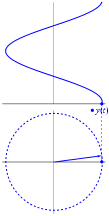
Fig 3
A phasor can be seen as a vector rotating about the origin in a complex plane. The cosine function is the projection of the vector onto the real axis. Its amplitude is the modulus of the vector, and its argument is the total phase \omega t+\theta. The phase constant \theta represents the angle that the vector forms with the real axis at t = 0.
Capacitors in AC circuits
Earlier in a previous Atom, we studied how the voltage and the current varied with time. If the AC supply is connected to a resistor, then the current and voltage will be proportional to each other. This means that the current and voltage will "peak" at the same time. We say that the current and voltage are in phase.
When a capacitor is connected to an alternating voltage, the maximum voltage is proportional to the maximum current, but the maximum voltage does not occur at the same time as the maximum current. The current has its maximum (it peaks) one quarter of a cycle before the voltage peaks. Engineers say that the "current leads the voltage by 90∘". This is shown in .
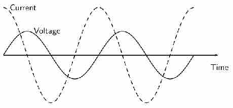
Fig 2
The current peaks (has its maximum) one quarter of a wave before the voltage when a capacitor is connected to an alternating voltage.
For a circuit with a capacitor, the instantaneous value of V/I is not constant. However, the value of Vmax/Imax is useful, and is called the capacitive reactance (XC) of the component. Because it is still a voltage divided by a current (like resistance), its unit is the ohm. The value of XC (C standing for capacitor) depends on its capacitance (C) and the frequency (f) of the alternating current.
The capacitor is affecting the current, having the ability to stop it altogether when fully charged. Since an AC voltage is applied, there is an rms current, but it is limited by the capacitor. This is considered to be an effective resistance of the capacitor to AC, and so the rms current Irms in the circuit containing only a capacitor C is given by another version of Ohm's law to be
Phase representation
Since the voltage across a capacitor lags the current, the phasor representing the current and voltage would be give as in . In the diagram, the arrows rotate in counter-clockwise direction at a frequency
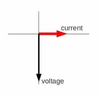
Fig 4
Phasor diagram for an AC circuit with a capacitor