Thin Lenses and Ray Tracing
Ray tracing is the technique of determining or following (tracing) the paths that light rays take. Experiments, as well as our own experiences, show that when light interacts with objects several times as large as its wavelength, it travels in straight lines and acts like a ray. (A ray is simply a straight line that originates at a point. ) Its wave characteristics are not pronounced in such situations. Since the wavelength of light is less than a micron (a thousandth of a millimeter), it acts like a ray in the many common situations in which it encounters objects larger than a micron, such as lenses.
For rays passing through matter, the law of refraction is used to trace the paths. Here we use ray tracing to help us understand the action of lenses in situations ranging from forming images on film to magnifying small print to correcting nearsightedness. While ray tracing for complicated lenses, such as those found in sophisticated cameras, may require computer techniques, there is a set of simple rules for tracing rays through thin lenses. A thin lens is defined to be one whose thickness allows rays to refract, as illustrated in , but does not allow properties such as dispersion and aberrations. An ideal thin lens has two refracting surfaces but the lens is thin enough toassume that light rays bend only once. Another way of saying this is that the lens thickness is much much smaller than the focal length of the lens. A thin symmetrical lens has two focal points, one on either side and both at the same distance from the lens. (See . ) Another important characteristic of a thin lens is that light rays through its center are deflected by a negligible amount, as seen in the center rays in the first two figures. The treatment of a lens as a thin lens is known as the "thin lens approximation. "
Convex Lens
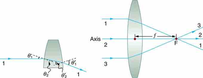
Rays of light entering a converging lens parallel to its axis converge at its focal point F. (Ray 2 lies on the axis of the lens. ) The distance from the center of the lens to the focal point is the lens's focal length f. An expanded view of the path taken by ray 1 shows the perpendiculars and the angles of incidence and refraction at both surfaces.
Thin Lens
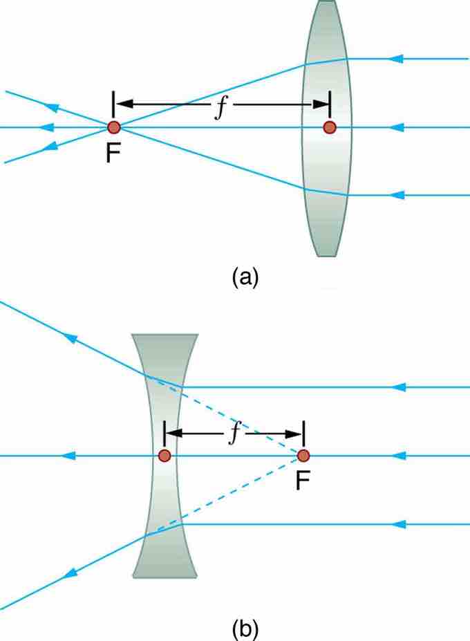
Thin lenses have the same focal length on either side. (a) Parallel light rays entering a converging lens from the right cross at its focal point on the left. (b) Parallel light rays entering a diverging lens from the right seem to come from the focal point on the right.
Rules for Ray Tracing
Using paper, pencil, and a straight edge, ray tracing can accurately describe the operation of a lens. The rules for ray tracing for thin lenses are based on the illustrations included in this section:
- A ray entering a converging lens parallel to its axis passes through the focal point F of the lens on the other side. ( See rays 1 and 3 in . )
- A ray entering a diverging lens parallel to its axis seems to come from the focal point F. (See rays 1 and 3 in . )
- A ray passing through the center of either a converging or a diverging lens does not change direction. (See ray 2 in and . )
- A ray entering a converging lens through its focal point exits parallel to its axis. (The reverse of rays 1 and 3 in . )
- A ray that enters a diverging lens by heading toward the focal point on the opposite side exits parallel to the axis. (The reverse of rays 1 and 3 in ).
Diverging Lens
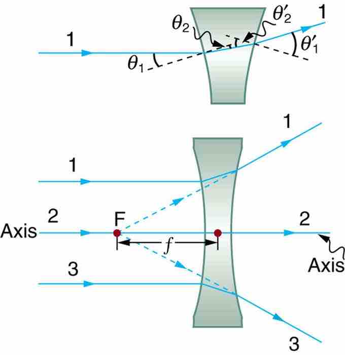
Rays of light entering a diverging lens parallel to its axis are diverged, and all appear to originate at its focal point F. The dashed lines are not rays—they indicate the directions from which the rays appear to come. The focal length f of a diverging lens is negative. An expanded view of the path taken by ray 1 shows the perpendiculars and the angles of incidence and refraction at both surfaces.