Physics
Textbooks
Boundless Physics
The Basics of Physics
Solving Physics Problems
Physics Textbooks Boundless Physics The Basics of Physics Solving Physics Problems
Physics Textbooks Boundless Physics The Basics of Physics
Physics Textbooks Boundless Physics
Physics Textbooks
Physics
Concept Version 6
Created by Boundless

General Problem-Solving Tricks

Free body diagrams use geometry and vectors to visually represent the problem.

Learning Objective

  • Construct a free-body diagram for a physical scenario


Key Points

    • A free body diagram lets you visually isolate the problem you are trying to solve, and simplify it into simple geometry and trigonometry.
    • When drawing these diagrams, it is helpful to only draw the body it self, and the forces acting on it.
    • Drawing other objects and internal forces can condense the diagram and cause it to be less helpful.

Terms

  • static

    Fixed in place; having no motion.

  • dynamic

    Changing; active; in motion.


Example

    • See. A simple free body diagram, shown above, of a block on a ramp illustrates this. All external supports and structures have been replaced by the forces they generate. These include: mg: the product of the mass of the block and the constant of gravitation acceleration: its weight. N: the normal force of the ramp. Ff: the friction force of the ramp. The force vectors show direction and point of application and are labeled with their magnitude. It contains a coordinate system that can be used when describing the vectors. Some care is needed in interpreting the diagram. The line of action of the normal force has been shown to be at the midpoint of the base but its true location can only be found if sufficient further data is given. The diagram as it stands would need to be modified were we told that the block is in equilibrium. There is a potential difficulty also with the arrow representing friction. The engineer who drew this diagram has used the tip of the arrow to indicate the point of application of a force. (See the other force arrows in the diagram). Now, the tip of the friction arrow is at the highest point of the base. The intention however is not to indicate that the friction acts at that point. The engineer in this instance has assumed a rigid body scenario and that the friction force is a sliding vector and thus the point of application is not relevant. The engineer has tried to indicate that the friction acts all along the whole base by drawing an arrow all along the base but such artistic ploys are a matter of personal choice.

Full Text

In physics, most problems are solved much more easily when a free body diagram is used. This uses geometry and vectors to visually represent to problem, and trigonometry is also used in determining horizontal and vertical components of forces and objects.

Purpose: Free body diagrams are very helpful in visually identifying which components are unknown, where the moments are applied, and help analyze a problem, whether static or dynamic.

How to Make A Free Body Diagram

To draw a free body diagram, do not worry about drawing it to scale, this will just be what you use to help yourself identify the problems. First you want to model the body, in one of three ways:

  • As a particle. This model may be used when any turning effects are zero or have zero interest even though the body itself may be extended. The body may be represented by a small symbolic blob and the diagram reduces to a set of concurrent arrows. A force on a particle is a bound vector.
  • rigid extended. Stresses and strains are of no interest but turning effects are. A force arrow should lie along the line of force, but where along the line is irrelevant. A force on an extended rigid body is asliding vector.
  • non-rigid extended. The point of application of a force becomes crucial and has to be indicated on the diagram. A force on a non-rigid body is a bound vector. Some engineers use the tail of the arrow to indicate the point of application. Others use the tip.

Do's and Don'ts

What to include: Since a free body diagram represents the body itself and the external forces on it. So you will want to include the following things in the diagram:

  • The body: This is usually sketched in a schematic way depending on the body - particle/extended, rigid/non-rigid - and on what questions are to be answered. Thus if rotation of the body and torque is in consideration, an indication of size and shape of the body is needed.
  • The external forces: These are indicated by labelled arrows. In a fully solved problem, a force arrow is capable of indicating the direction, the magnitude the point of application. These forces can be friction, gravity, normal force, drag, tension, etc...

Do not include:

  • Do not show bodies other than the body of interest.
  • Do not show forces exerted by the body.
  • Internal forces acting on various parts of the body by other parts of the body.
  • Any velocity or acceleration is left out.
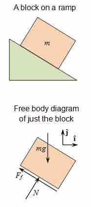
How To Solve Any Physics Problem

Learn five simple steps in five minutes! In this episode we cover the most effective problem-solving method I've encountered and call upon some fuzzy friends to help us remember the steps.

Free Body Diagram

Use this figure to work through the example problem.

[ edit ]
Edit this content
Prev Concept
Trigonometry
Defining Kinematics
Next Concept
Subjects
  • Accounting
  • Algebra
  • Art History
  • Biology
  • Business
  • Calculus
  • Chemistry
  • Communications
  • Economics
  • Finance
  • Management
  • Marketing
  • Microbiology
  • Physics
  • Physiology
  • Political Science
  • Psychology
  • Sociology
  • Statistics
  • U.S. History
  • World History
  • Writing

Except where noted, content and user contributions on this site are licensed under CC BY-SA 4.0 with attribution required.