Phasors
Complex numbers play an important role in physics. Usually, complex numbers are written in terms of their real part plus the imaginary part. For example,
In physics, a phase vector, or phasor, is a representation of a sinusoidal function whose amplitude (A), frequency (ω), and phase (θ) are time-invariant, as diagramed in . Phasors separate the dependencies on A, ω, and θ into three independent factors. This can be particularly useful because the frequency factor (which includes the time-dependence of the sinusoid) is often common to all the components of a linear combination of sinusoids. In those situations, phasors allow this common feature to be factored out, leaving just the A and θ features. The result is that trigonometry reduces to algebra, and linear differential equations become algebraic ones. The term phasor therefore often refers to just those two factors.

Phasor Diagram
An example of series RLC circuit and respective phasor diagram for a specific ω. Electrical engineers, electronics engineers, electronic engineering technicians and aircraft engineers all use phasor diagrams to visualize complex constants and variables (phasors). Like vectors, arrows drawn on graph paper or computer displays represent phasors.
Phasors are often used in electrical systems when considering voltages and currents that vary sinusoidally in time, such as in RLC circuits.
Definition
Sinusoids can be represented mathematically as the sum of two complex-valued functions:
or as the real part of one of the functions:
As indicated above, phasor can refer to either
Phasor Representation of Signals
There are two key ideas behind the phasor representation of a signal:
- a real, time-varying signal may be represented by a complex, time-varying signal; and
- a complex, time-varying signal may be represented as the product of a complex number that is independent of time and a complex signal that is dependent on time.
The signal:
illustrated in the figure below is a cosinusoidal signal with amplitude A, frequency, and phase θ. The amplitude A characterizes the peak-to-peak swing of 2A, the angular frequency ω characterizes the period T=2π/ω between negative- to-positive zero crossings (or positive peaks or negative peaks), and the phase θ characterizes the time τ=−θ/ω when the signal reaches its first peak. With so defined, the signal x(t) may also be written as
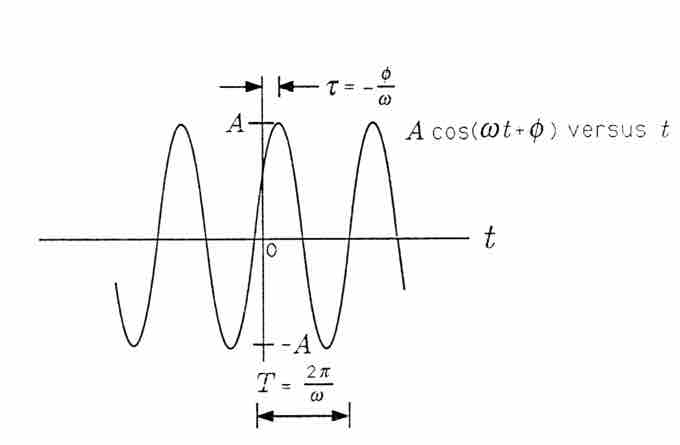
Cosinusoidal Signal
A Cosinusoidal Signal.
When τ is positive, then τ is a "time delay" that describes the time (greater than zero) when the first peak is achieved. When τ is negative, then τ is a "time advance" that describes the time (less than zero) when the last peak was achieved. With the substitution =2π/T we obtain a third way of writing x(t):
In this form the signal is easy to plot. Simply draw a cosinusoidal wave with amplitude A and period T; then strike the origin (t=0) so that the signal reaches its peak at τ. In summary, the parameters that determine a cosinusoidal signal have the following units:
- A, arbitrary (e.g., volts or meters/sec, depending upon the application)
- ω, in radians/sec (rad/sec)
- T, in seconds (sec)
- θ, in radians (rad)
- τ, in seconds (sec)
Sinusoidal Steady State and the Series RLC CircuitPhasors may be used to analyze the behavior of electrical and mechanical systems that have reached a kind of equilibrium called sinusoidal steady state.
In the sinusoidal steady state, every voltage and current (or force and velocity) in a system is sinusoidal with angular frequency ω. However, the amplitudes and phases of these sinusoidal voltages and currents are all different.
For example, the voltage across a resistor might lead the voltage across a capacitor by 90∘ and lag the voltage across an inductor by 90∘. In order to make our application of phasors to electrical systems concrete, we consider the series RLC circuit illustrated in . The arrow labeled i(t) denotes a current that flows in response to the voltage applied.
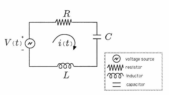
Series RLC Circuit
Series RLC Circuit.
We will assume that the voltage source is an audio oscillator that produces the voltage:
We represent this voltage as the complex signal:
and give it the phasor representation,
We then describe the voltage source by the phasor V and remember that we can always compute the actual voltage by multiplying by eiωt and taking the real part.