Physics
Textbooks
Boundless Physics
Circuits and Direct Currents
RC Circuits
Physics Textbooks Boundless Physics Circuits and Direct Currents RC Circuits
Physics Textbooks Boundless Physics Circuits and Direct Currents
Physics Textbooks Boundless Physics
Physics Textbooks
Physics
Concept Version 9
Created by Boundless

Impedance

Impedance is the measure of the opposition that a circuit presents to the passage of a current when a voltage is applied.

Learning Objective

  • Express the relationship between the impedance, the resistance, and the capacitance of a series RC circuitĀ in a form of equation


Key Points

    • The advantage of assuming that sources have complex exponential form is that all voltages and currents in the circuit are also complex exponentials, having the same frequency as the source.
    • The major consequence of assuming complex exponential voltage and currents is that the ratio (Z = V/I) for each element does not depend on time, but does depend on source frequency.
    • For a series RC circuit, the impedance is given as $Z = \sqrt{R^2+(\frac{1}{\omega C})^2}$ .

Terms

  • impedance

    A measure of the opposition to the flow of an alternating current in a circuit; the aggregation of its resistance, inductive and capacitive reactance. Represented by the symbol Z.

  • AC

    Alternating current.

  • capacitor

    An electronic component capable of storing an electric charge, especially one consisting of two conductors separated by a dielectric.

  • resistor

    An electric component that transmits current in direct proportion to the voltage across it.


Full Text

Rather than solving the differential equation relating to circuits that contain resistors and capacitors, we can imagine all sources in the circuit are complex exponentials having the same frequency. This technique is useful in solving problems in which phase relationship is important. The phase of the complex impedance is the phase shift by which the current is ahead of the voltage.

Complex Analysis

For an RC circuit in , the AC source driving the circuit is given as:
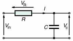
Series RC Circuit

Series RC circuit.

$v_{in}(t) = V e^{j \omega t}$,

where V is the amplitude of the AC voltage, j is the imaginary unit (j2=-1), and $\omega$ is the angular frequency of the AC source. Two things to note:

  1. We use lower case alphabets for voltages and sources to represent that they are alternating (i.e., we use vin(t) instead of Vin(t)).
  2. The imaginary unit is given the symbol "j", not the usual "i". "i" is reserved for alternating currents.

Complex Impedance

The advantage of assuming sources take this form is that all voltages and currents in the circuit are also complex exponentials (having the same frequency as the source). To appreciate the reason for this, we can investigate how each circuit element behaves when either the voltage or current is a complex exponential. For the resistor, $v = Ri$. From our voltage given above, $i = \frac{V}{R} e^{j \omega t}$. Thus the resistor's voltage is a complex, as is the current with an amplitude $I = \frac{V}{R}$. For a capacitor, $i = C \frac{dv}{dt}$. Letting the voltage be a complex exponential we have $i = j \omega CV e^{j \omega t}$. The amplitude of this complex exponential is $I = j \omega CV$.

The major consequence of assuming complex exponential voltage and currents is that the ratio $Z = \frac{V}{I}$ for rather than depending on time each element depends on source frequency. This quantity is known as the element's (complex) impedance. The magnitude of the complex impedance is the ratio of the voltage amplitude to the current amplitude. Just like resistance in DC cases, impedance is the measure of the opposition that a circuit presents to the passage of a current when a voltage is applied. The impedance of a resistor is R, while that of a capacitor (C) is $\frac{1}{j \omega C}$. In the case of the circuit in , to find the complex impedance of the RC circuit, we add the impedance of the two components, just as with two resistors in series: $Z = R + \frac{ 1}{j \omega C}$.

Finding Real Currents and Voltages

Since $e^{j\omega t} = cos(\omega t) + j sin(\omega t)$, to find the real currents and voltages we simply need to take the real part of the i(t) and v(t). The (real value) impedance is the real part of the complex impedance Z. For a series RC circuit, we get $Z = \sqrt{R^2+(\frac{1}{\omega C})^2}$. We see that the amplitude of the current will be $V/Z = \frac{V}{\sqrt{R^2+(\frac{1}{\omega C})^2}}$.

[ edit ]
Edit this content
Prev Concept
Resistors and Capacitors in Series
Phase Angle and Power Factor
Next Concept
Subjects
  • Accounting
  • Algebra
  • Art History
  • Biology
  • Business
  • Calculus
  • Chemistry
  • Communications
  • Economics
  • Finance
  • Management
  • Marketing
  • Microbiology
  • Physics
  • Physiology
  • Political Science
  • Psychology
  • Sociology
  • Statistics
  • U.S. History
  • World History
  • Writing

Except where noted, content and user contributions on this site are licensed under CC BY-SA 4.0 with attribution required.